Vibration sensors
Vibrations monitoring and analysis are at the core of most condition based monitoring systems as vibrations and harmonic signatures are often the first indication of an impending motor failure.
ADI OtoSense™ Smart Motor Sensors are equipped with a Vibration X-axis (tangential vibration) sensor as well as a Vibration Z-axis (axial vibration) sensor (see Table 2 for specifications).
Since each motor has a unique vibrational profile, the ADI OtoSense™ SMS first determines a motor’s baseline operating condition during the learning period (see About the learning period).
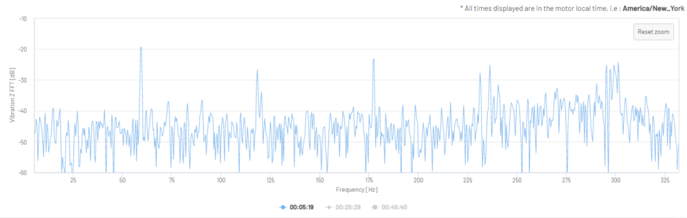
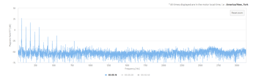
The ADI OtoSense™ SMS Cloud platform, mobile application, and API provide both time and frequency domain data. Fast Fourier transform (FFT) data allows for the quick identification of discrete frequency peaks.
Table 2: Vibration Sensor Specifications
| Sensor Type | Amplitude Range | Frequency Range | Sampling Frequency | Number of Samples | Data Formats | Data Type |
| X-Axis Vibration Y-Axis Vibration |
±40 g. | 1Hz to 3.1 kHz | 6.25kHz | 15kS – 2.4 seconds | waveform, FFT, rms | Float |
Figure 8: Vibration X-Axis Time Waveform in m/s2 (three samples, overlaid)
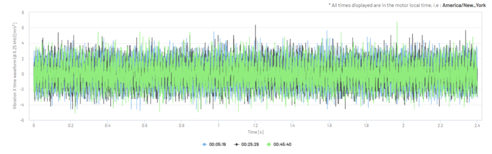
Figure 9: Vibration X-Axis FFT in dB
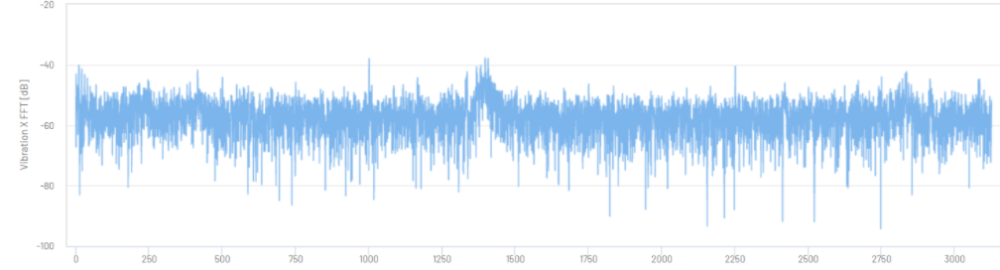
Figure 10: Vibration Z-Axis Time Waveform in m/s2 (one 2.4 second sample)
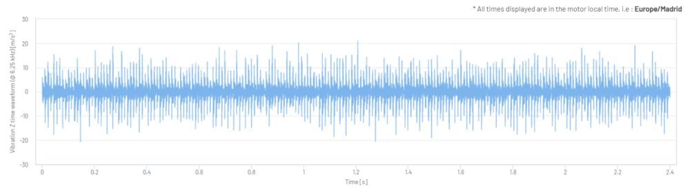
Figure 11 and 12: Vibration Z-Axis Time Waveform in m/s2 (one 2.4 second sample, zoomed-in views)
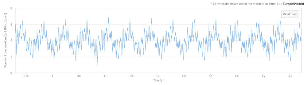
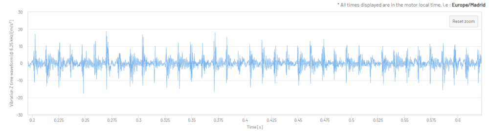
Figure 13: Vibration Z-Axis Fast Fourier Transform in dB (one 2.4 second sample)
Magnetic field sensor
Measurement of the magnetic field around a motor allows for insights into electrical and mechanical motor performance issues.
ADI OtoSense™ Smart Motor Sensors are equipped with a single magnetic field sensor (see Table 3 for specifications).
Table 3: Magnetic Field Sensor Specifications
| Sensor Type | Sampling Frequency | Number of Samples | Data Formats | Data Type |
| Magnetic Field | 6.25kHz | 15kS – 2.4 seconds | waveform, FFT | Float |
Figure 14: Magnetic Field Time Waveform in mV (one 2.4 second sample)
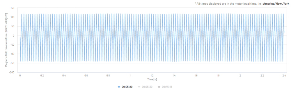
Figure 15: Magnetic Field Time Waveform in mV (one 2.4 second sample, zoomed-in view)
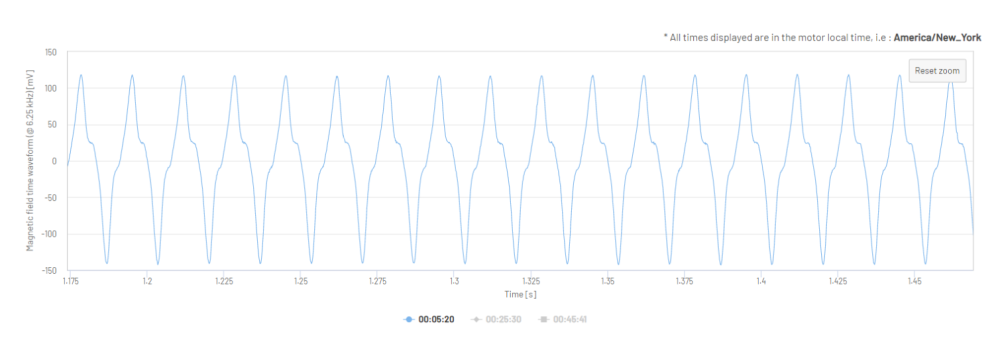
Figure 16: Magnetic Field Time Waveform in mV (three 2.4 second samples, overlaid)
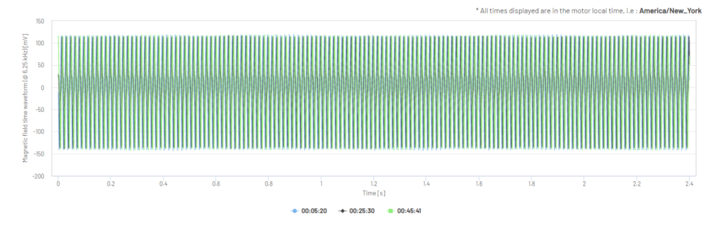
Figure 17: Magnetic Field Fast Fourier Transform in dB (one 2.4 second sample)
Temperature sensors
The majority of motor faults will eventually result in high temperatures. These high temperatures can be an indication of the excessive friction within a motor or fan issues. ADI OtoSense Smart Motor Sensors™ are equipped with two on-board temperature sensors: an environment temperature sensor and a motor temperature sensor (see Table 4).
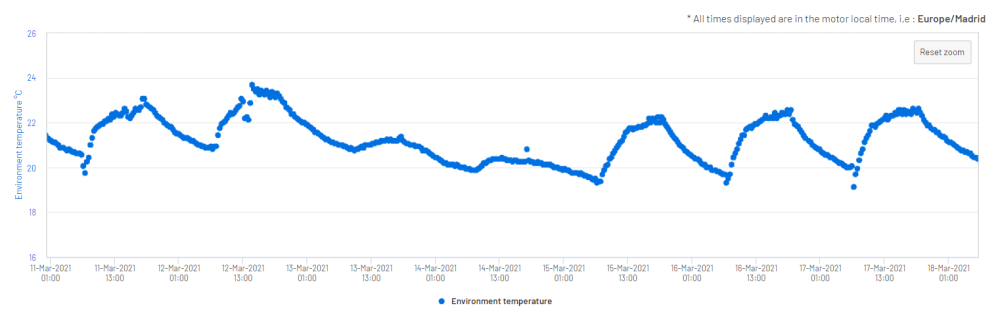
The environment temperature sensor allows for ADI OtoSense™ SMS to take ambient operating conditions, such as sunlight exposure, into account when assessing a motor’s temperature status.
Table 4: Temperature Sensor Specifications
| Sensor Type | Measurement Range | Precision Accuracy | Data Type |
| Environment Temperature Motor Temperature |
-40ºC to +150ºC | 0.0625 ± 0.5ºC | Float |
Figure 18: Motor Temperature in °C
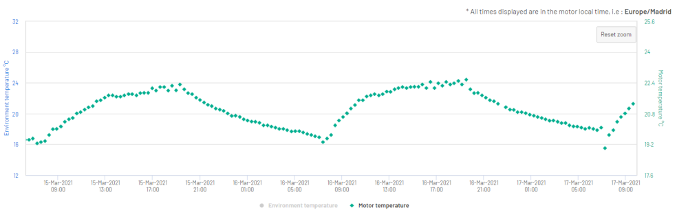
Figure 19: Environment Temperature in °C